Line Printing
The printing workflows print parallel lines with a fixed width on a surface.
This is done by approaching the probe to the surface and then performing an x/y motion while keeping the probe in contact.
There are two workflows available
Line Printing Workflow
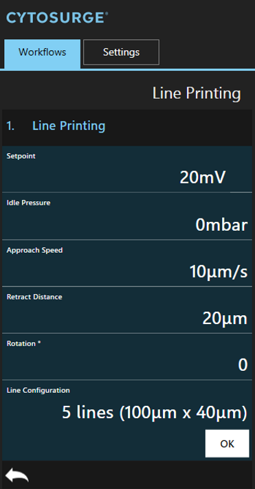
This workflow prints lines on a surface and using the same speed and pressure configuration for every line.
Positioning, dimension and count of the lines can be configured either inline or in the configuration window.
| Parameter | Description |
|---|---|
Pressure |
The pressure to be applied while the probe is in contact |
Idle_Pressure |
The pressure to be applied while the probe is either approach or retracting |
Rotation |
[Degree] Rotates the configured line pattern along its center position. Zero degree causes the lines to be printed along the X axis. |
Line_Shift |
The distance between two parallel lines to use when generating the line pattern |
Line_Length |
The width of a single line to use when generating the line pattern |
The probe’s initial x/y position is restored after the print operation finished. This allows to print over the structure that was just printed or printing e.g. the same structure with different rotations.
Line Print Calibration Workflow
This workflow prints lines on a surface and using either an increased print pressure per line or an increased print speed per line.
It allows to quickly determine reasonable parameter values and to fine-tune line widths.
The printing procedure itself is the same as used in line printing workflow.
Notable parameters are
| Parameter | Description |
|---|---|
Pressure, Pressure_Increment |
Defines which values to use for “Pressure Calibration”. The first line’s print pressure is set to Pressure and is increased by Pressure_Increment for every additional line |
Print_Speed, Speed_Increment |
Defines which values to use for “Speed Calibration”. The first line’s motion velocity is set to Print_Speed and is increased by Speed_Increment for every additional line |