System Calibration
Important
Carefully read the entire chapter before starting the calibration.
The calibration should only be carried out by trained operators.
The system must be calibrated after being assembled to determine and compensate for mechanical tolerances. The software comes with calibration methods included which must be run before the system can be operated.
- Ensure that all three axes can move to to their extreme positions
- Ensure the head is mounted on the axis
- Ensure computer is connected to the controller by USB
- Power on the system. On initial power-on, the controller requires around 40 seconds until all components have booted
- Start the software
- Load the maintenance workflows
- The workflows should be run in the order they are listed in this document
Note
The workflows described below are only available in Maintenance mode. To enter it, open the console by pressing ctrl+alt+c.
Then, type in scriptmanager maintenance on and press enter which loads the workflows described below. scriptmanager maintenance off removed them again.
Stage handling during calibration
Plates must be inserted or removed for certain workflows at a time at which the system is not fully configured yet. However, operating with an incompletely configured system bears the risk of probe crashes. The following methods are always available though:
- Plates can be removed or installed with the exchange plates workflow. Make sure to retract the microscope’s objective in case it’s higher than the plate’s border.
- Inter-plate moves can be performed by configuring a plate as WellPlate with really high
Content Level. One can then switch between the areas represented by wells without having to worry that the probe touches the plate.
In case of an unset z-level most movement commands are either disabled or return an error (E_INVALID_ARG). The available z range is however displayed in a warning message during startup and enables the operator to temporarily set an estimated z level by adding 4mm to the lower bound and save it to the configuration file as PlaceHolderLevel (see the note below and the section Z-Calibration).
Configuration File
Some parameters must be adjusted in a configuration file. It is located at C:\ProgramData\Cytosurge\CYuiSettings.xml. This xml formatted configuration file can be edited with notepad. Make sure the software is not running when opening and/or changing values. Otherwise, changes to the file performed by the software might get overwritten. Furthermore, the containing folder is not shown in Windows Explorer (hidden folder). You can bypass this restriction by entering the full path to the file directly in e.g. notepad.
Stage Dragging
Stage dragging is allowed during the execution of most actions. Use with care. Incompletely configured systems might cause unexpected movements. Also, do not start a drag operation while another movement is pending.
Camera Alignment
Prerequisites
- Camera is installed
- A plate with transparent material is installed that contains an identifiable object (e.g. a slightly dusty well plate)
- Plate configuration (Exchange Plates) is adjusted to match the transparent plate
- Illumination is turned on
Process
- Using the navigation tool, move over a transparent plate area
- Run the workflow
- The stage begins to repeatedly move along its x axis
- Focus on the plate and select reference point (a previously drawn indicator, a piece of dust, etc.)
- Drag the overlaid, semi-transparent rectangle so its border appears above the reference point
- Rotate the camera until the reference point moves parallel to the border of the rectangle. You can use the mouse wheel to change the rectangle’s size.
- Fix the camera
General Alignment
The camera must be aligned so that a cantilever’s chip is located at the bottom of the reported image frame. This might not be possible if the head has not been centered yet. However, for setup purposes it is important that camera is aligned anyway even if the error is 90, 180 or 270 degrees. If it turns out that the chip is located on the wrong side, one can adjust the alignment and run this step again.
Optical Microscope Configuration
If the driver for Zeiss mtb observer or Olympus IX83 was installed, no microscope specific configuration have to be performed.
However, the list of available lenses must be registered if the virtual microscope driver was installed. To do so, run “Setup Microscope”.
- Register each lens. Provide a name and the theoretical magnification. You can calibrate the precise magnification later on.
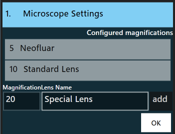
- Restart the software
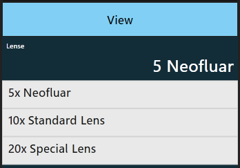
- Verify that the lens configuration is seen by the system. Check the available lenses in the settings menu, category ‘View’.
X-Y Calibration (Head)
This step is carried out in order to position the Stage Z module according to a reference probe. By doing so it can be ensured that the probe remains in the field of view even in highly magnified setups.
Prerequisites
- Camera is aligned
- Head is mounted
- Reference probe is mounted
- No plates are installed
Recommended calibration process
- The software in Maintenance mode should be started to lower the probe and display the reference structure. The probe is placed 2.5 mm above its minimum position.
- Switch to the lowest magnification setting
- Choose Calibrate XY (head) in the workflows list, press OK - the probe gets calibration position
- Use the alignment screws to move the probe’s tip to the reference structure overlaid on the screen
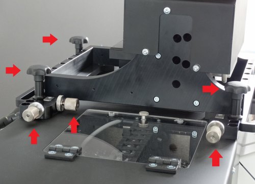
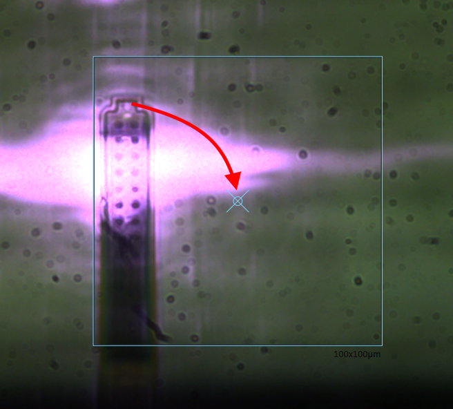
- Increase the optical magnification and readjust the module’s position (step 3) until the the probe appears centered in the maximum magnification setting
- Tighten the lock screws and fix the module’s position with the provided screws
- When centering the probe with the adjustment screws, one should pay attention to minimize the rotation of the head (use low magnification to check), that is, move x-screws by a similar distance
- Go to the next step
X-Y Calibration (Stage)
The purpose of this step is to determine the coordinates of a certain reference point on the mounted stage. Doing so improves movement precision when moving in the x-y plane. A probe sitting in the probe holder serves as reference position.
Prerequisites
- Camera is aligned
- Head is mounted and centered
- A probe plate with a probe in location A1 is installed on either side
- The head’s built in light source is turned on
Process
Run the workflow. Press on the appropriate reference position and start.
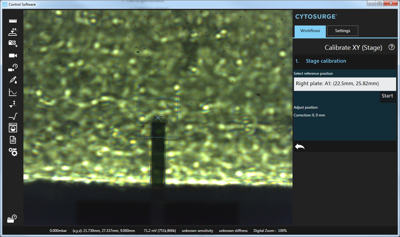
Focus on the probe.
Then use the provided components for alignment:
- Use the microscope’s focus level to bring the probe into focus.
- Arrows: the arrow navigation is used to move the stage so as to place the probe at the center of the screen, indicated by the vertical/horizontal lines (adjust the step size to control the distance traveled in each step)
- Correction: when the probe is in the exact center of the screen, the correction result represents the x-y offset to be noted
Note the displayed Correction and update BottomCameraOffset in the configuration file, omitting the unit, e.g. <BottomCameraOffset>0.92,-0.34</BottomCameraOffset>
Note
Restart of the software is required to apply the configuration file changes
Note
If the camera is not sensitive enough to show the probe as above, use the probe tool to manually advance the probe towards the probe plate. Note that the advance operation must be canceled manually as otherwise the mounted tip crashes into the probe sitting on plate.
Z-Calibration
This step is carried out to determine the exact height of the probeholder.
Prerequisites
- Head and stage have been calibrated (XY)
- At least one probe holder plate is installed. Calibration can only be performed on empty slots!
- A probe is mounted
The process consists of the following steps:
- Select probe holder slots at which z measurements will be taken
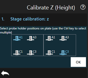
- For each selected slot:
- (Automatic) retraction of the Z-axis
- (Automatic) placement of the head above the selected slot.
- (Manual) carefully lower the head by hand in z-direction until the head touches the probeholder. Use as little force as possible.
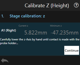
- (Automatic) computation of minimum z position
- Move to the next slot
- Press Done and restart the software
Note Minimum z from the software, subtract 4.25mm and update PlateHolderLevel in the configuration file, including the unit, e.g. <PlateHolderLevel>-37.641mm</PlateHolderLevel>
Note
4.25mm = (-25.3+20.94+0.11: holder.rev9 height + how much consumable.v4rev10.16 sticks out + height of the o-ring(screw v10.16))
Note
Restart of the software is required to apply the updated z level values
Calibrate Pixel Size
This step measures and configures the actual magnification as displayed in the software. It might differ slightly from the one reported by the objectives due to various factors. It is important to determine the effective magnification as otherwise digitally overlaid content appears not sized correctly or point selection (e.g. with crosshair) has small offsets.
Prerequisites
- Camera is installed and aligned
- Transparent plate is installed
Process
- Run the workflow
-
The action displays the currently available objectives. Select the one to be calibrated. Continue.
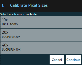
- List of available objectives. The already calibrated ones are displayed with their corrected magnification
-
Focus on the plate and select reference point (a previously drawn indicator, a piece of dust, etc.)
- Configure the two offsets, (ax,ay) and (bx,by), according to which the stage will be moved. Choose the points so they will be visible in the current field of view but are far enough from each other to allow precise selection. Continue.
- Select the reference point with the crosshair. Continue.
- Select the reference point again with the crosshair. Continue.
-
The measured magnification is shown. Adjust if necessary.
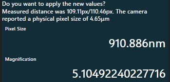
- Effective magnification of a 5x objective. You can edit the value which is about to be applied by clicking on the magnification.
-
Repeat 2) for every installed objective
Note
Restart of the software is required to apply the calibration values.
Calibrate Alignment Motor
Process
- Run the workflow
- Select the motor type to be calibrated
-
Adjust the calibration position if required. The default values, updated when the motor type is set, are usually fine.
-
Run the action by pressing ‘OK’
- Repeat for every motor type
Note
The calibration (frequency tuning) is ideally performed when the head is running at its operating temperature. This state is reached after one hour.
Recover probe loss during the calibration process
The system must not be operated without probe attached except for Z Level Calibration. If the probe gets lost and the system configuration is not yet complete, one must not try to grip a new probe with the gripping workflow as there exists a high risk of damaging hardware components.
Instead, following procedure must be applied:
- Turn off the controller
- Remove the head cover
- Remove the data/power cable and the pressure cable and detach the head from the axis
- Ensure you have a probe ready to be mounted
-
Manually open the grippers by inserting a lever into the gripper’s hole and pushing it up. Install the probe and let the grippers close again. Ensure the sealing screw enters the probe reservoir and does not rest on the reservoir’s border.
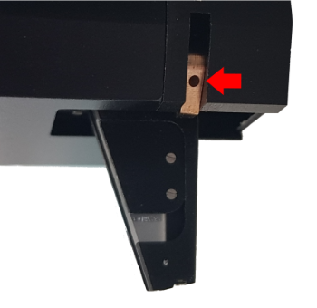
- Where to insert the lever for open the grippers
-
Fix the head onto the axis, connect the cables and add the cover
- All head relevant calibrations must be performed again as the head was moved
Rail Lubrication
All rails have to be oiled at least once per year to ensure long term functionality. The old oil has to be removed first then new oil is put on the rails. The rail lubrication workflow will distribute the oil automatically.
Prerequisites
- Head is mounted
Process
- Follow the lubrication instructions
- Run the workflow
- The head begins to repeatedly move up and down, pausing after reaching the upper or lower limit
- After about 5 minutes, the stage begins to repeatedly move along its X and Y axes, pausing after reaching an axis limit
- Steps 3 and 4 are repeated for 60 minutes