Preparation Advanced
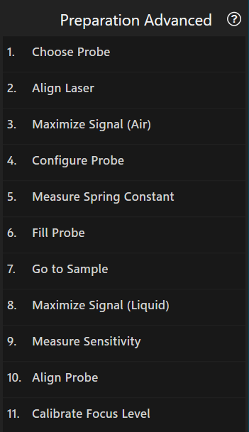
The system needs to be set up before you can perform any FluidFM experiment. This workflow guides you through the necessary steps. It will take up to 5 minutes and should be repeated every time a new probe is used. Advanced users can freely jump between steps.
Note
Remember to actually fill the probe before inserting it into the holder. Refer to the forum for more information. 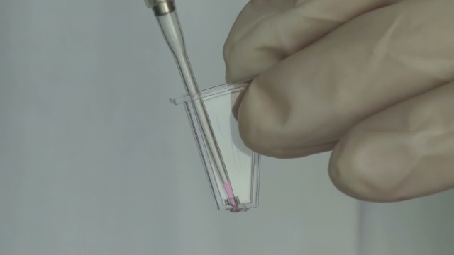
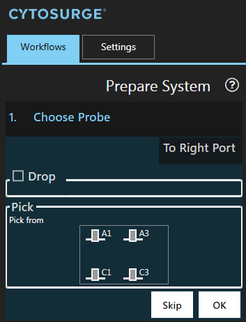
1. Choose Probe
In this step you are dropping and/or gripping a probe. Both operations are performed in one run to minimize the time during which there is no probe mounted on the system.
Note
This step cannot be run if the worktable contains no probe holder. To update the plate configuration run Exchange Plates in the menu “Workflows”. The probe holder is usually placed on the right side.
If you need access to the probe holder, press To Right Port (or To Left Port) which moves the plate to one of the ports.
Insert the probe into a slot:
Drop
If you already have a probe mounted, you have to remove it first. To do so, choose an empty slot in which to place that probe by clicking on it.

Attention
Make sure that the slot you are about to drop to is empty.
Note
The checkbox ‘Drop’ is automatically checked if a probe is mounted. However, if the system does not detect an already mounted probe you can enforce a drop operation by checking ‘Drop’.
Pick
Choose the probe to be picked by clicking on the corresponding probe icon.
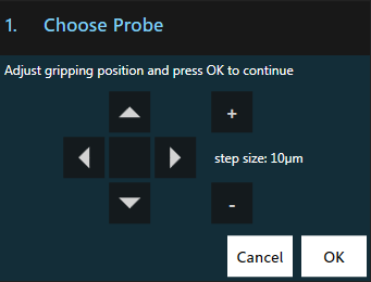
Press OK to start the probe exchange process.
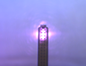
The system pauses right before the gripping operation. A rectangle is shown allowing you to correct the positioning before the grip operation. The positioning can be either corrected by dragging the stage or using the Navigation arrows.
Note
If you don’t see the probe, check if the light is turned on and the microscope focuses on the probe. You can change the internal illumination in the menu “Settings”, category “Stage”, parameter “Illumination”.
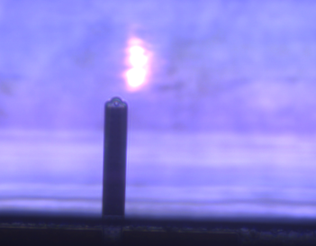
- Example of a successful grip operation: The probe becomes blurry as it moves into the head when the gripping mechanism closes.
1.1. Air Tightness Test
The air tightness test has to be performed every time a probe is mounted.
Automatic Test
After the probe has been mounted, the system automatically performs an air tightness test. It applies 20mbar and measures the average flow. If the absolute flow is greater than 0.2Pa, a warning is displayed:
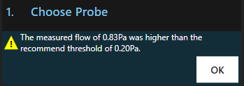
This means the probe is not correctly mounted which could lead to spillage and unreachable pressure values. To fix this, try repeating the gripping two to three times.
Note
If your system doesn’t support measuring flows or if the pressure controller isn’t ready, the air tightness test can’t be performed and needs to be done manually.
Manual Test
If your system doesn’t support measuring flows, you have to perform the air tightness test manually.
- Load the oscilloscope and the pressure tool
- Launch the flowsensor’s software “Sensirion USB RS485 Sensor Viewer”
- In the field
Sensor, selectSDP 6xx Seriesand pressRun
- In the field
- Apply 20mbar and check the flow in the Sensirion application
- If the reported flow shows more than +/- 0.2Pa while the oscilloscope shows 20mbar, it means that the probe is not properly connected. The experiment should not be continued due to the risk of spillage. Also, certain pressure values might not be reachable
- In such a case, repeat the gripping two to three times.
2. Align Laser
The laser has to be aligned with the tip of the probe for the force feedback to work.
Further information
Because the spring constant measurement is only accurate in air, the laser alignment has to be performed while the probe is still in air even when the experiment is solely conducted in liquid.
- Ensure that the microscope is focused on the FluidFM probe
- Remove / slide out the infrared filter of your microscope camera
- Use the arrow navigation control in the dialog to adjust the laser beam such that it is deflected by the probe’s end as shown in the right picture:
| Before alignment | After alignment |
|---|---|
 |
 |
- Press
OKto proceed to the next step and put the infrared filter in place again.
3. Maximize Signal (Air)
This step optimizes the signal quality.
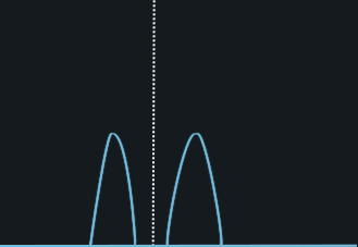
Choose “Center automatically” as the system can usually perform this step on its own. Dual sweep does incremental positioning, however, the plotted values are of less accuracy and therefore visualized as dashed line. In case of highly reflective backgrounds or non-standard probes, manual alignment is required.
Further information
For best force control, the signal needs to be maximized. Maximal signal is achieved when the two photo detectors within the FluidFM Omnium receive an equal amount of laser signal and are within 30% and 90% of their range. For that, a mirror inside the head has to be brought into the optimal position.
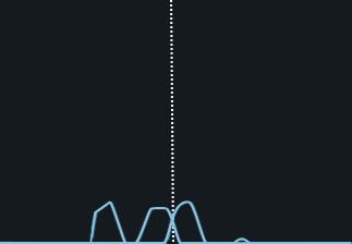
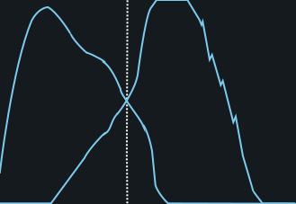
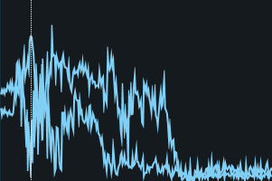
The automatic signal maximization gives you a feedback with a graph showing two curves - corresponding to each photodetector signal depending of the mirror position. The best position is where the two signals intersect. Below are a few examples:
| Good Signal | Bad Signals |
|---|---|
 |
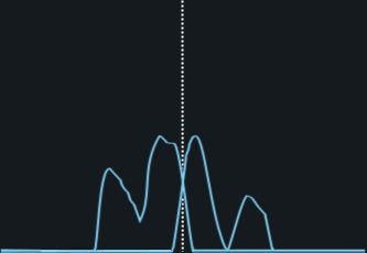     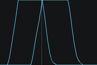 |
Center position
The center position (the dashed line in the graph) is not derived from the graph, but calculated inside the system and read out by the software. This explains the offset in dual scan mode.
If desired the graph can be saved to the result history using the  button.
Continue by pressing OK if there are overlapping curves with continuous segments in the intersecting area. Otherwise, realign the laser’s x/y position (previous step).
The mirror position for the laser is remembered for the medium ‘Air’ as shown with an icon in the status bar. Once you have maximized the signal for both, air and liquid, you may click on the icon in the status bar to switch between the media.

4. Configure Probe
Defines the probe’s specification. The values are used for subsequent calibrations.
This can be done in three different ways:
| Barcode (Recommended) | Selector | Manually |
|---|---|---|
Scan the barcode on the back of the package of the probe using the barcode reader to automatically download the specifications from the Cytosurge server. 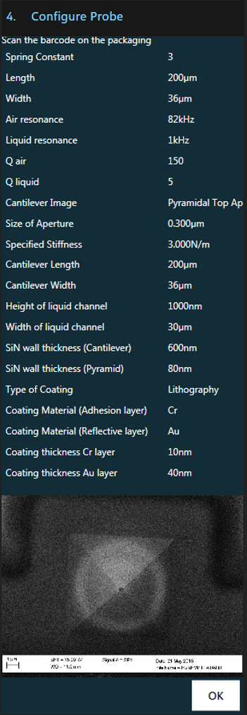 |
Select the mounted probe’s type yourself from a list. No data will be downloaded using this method. 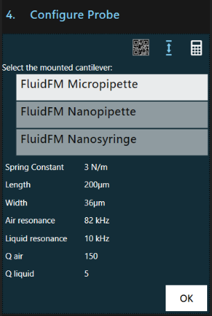 |
Enter the probe’s serial number manually to download the specifiactions from the Cytosurge server.  |
Note
Calibration values can be directly entered in the settings menu
5. Measure Spring Constant
This step measures and applies the spring constant. It is used to convert the deflection measured by the system to the actual force acting on the probe.
Avoid acoustic noise to achieve precise results. Ideally, the measurement is performed in air as measurements in liquid tend to be inaccurate due to low quality factors.
Start the automatic measurement of the spring constant with Measure.
The software then computes the spring constant from the measurement using the Sader method.
After configuring the probe the correction factor needed to compute the effective spring constant is already known and directly applied to the measurement:

You can still choose to use the measured value by unchecking Use effective value or overwrite the value by clicking on it.
Note
If Configure probe was skipped or an unkown probe type is used you will have to compute and apply the correction factor yourself.
Press “Apply” to accept the computed spring constant and use it to convert deflection to force.
You may then choose to save the the raw data of the measurement to the result history
Further information
The spring constant is a property of the probe and, as such, needs to be measured only once. The method used to determine the spring constant was developed by John Elie Sader. The spring constant for FluidFM probes typically ranges between 0.1 and 3 N/m.
6. Fill Probe
In this step you fill the probe with the liquid from the container.
Further information
With air in the probe, surface (tension) effects will prevent reproducible delivery of liquid from the probe.
It is therefore necessary to first fill the probe from the reservoir in order to both release and aspirate liquid.
Because it is sometimes difficult to exactly determine when the probe is filled, the video difference tool is automatically shown by this step.
- Configure the the video difference tool by selecting a rectangle around the cantilever in the video view or press
Fillto continue without the video difference tool. - Set the desired filling pressure using the left slider. 400-500mbar is usually enough and liquid in the cantilever can be seen within 10s after applying the pressure.

- Apply the pressure by pressing the
Fillbutton. - Wait until a change in the video difference tool is visible or use a fluorescence stain to control the outflow. Do not stop pressure application, yet.
- Move to the sample using the Navigation tool (see also the next step).
- Once the probe is in the liquid of the target well, stop pressure application by pressing the
Idlebutton. - Adjust the idle pressure using the right slider until the filling remains stable (i.e. is neither pushed back into nor flows out of the cantilever).
- The example video above shows a channel being filled around second 2 (color camera) and around second 15 (monochrome camera). The color change shown on the main video is minuscule and hard to spot, but clearly visible in the video difference tool. For bright field, we suggest the following imaging parameters: 20x objective, 20-25 ms exposure time, gain 0, 100% illumination from the Omnium.
7. Go to Sample
Move to your desired sample or well with the help of the Navigation tool.
Stop the pressure application only once you are in the liquid of the target well.
Proceed to the next step.
8. Maximize Signal (Liquid)
Further information
The ideal position of the mirror in the FluidFM Omnium depends of the refractive index of the medium your are working in. When you change the liquid it is therefore recommended to maximize the signal again.
This step is the same as the maximize signal step above, except that is conducted in the working liquid instead of air. Again, ensure that the result contains overlappping curves with continuous segments in the intersecting area or re-align the laser and repeat signal maximization.
The mirror position for the laser is remembered for the medium ‘Liquid’ as shown with an icon in the status bar. Once you have maximized the signal for both, air and liquid, you may click on the icon in the status bar to switch between the media.

9. Measure Sensitivity

In this step the probe automatically detects the surface and then performs the configured number of measurements.
You should perform the sensitivity calibration in the final medium of the experiment.
- Make sure that the cantilever is dust free and positioned above a hard surface (e.g. a Petri-dish without cells).
- Adjust the amount of sensitivity measurements to be averaged (recommended: 3).
- Start the calibration.
Further Information
In this step the probe deflection [m] is correlated with the measured signal change [V]. This is achieved by moving the probe by a specific distance against a hard surface and measuring the change in voltage recorded by the photo detector, thus relating the change in distance to voltage. Typical values for FluidFM probes are ~1.5 E-6 m/V.
Result
The averaged sensitivity is shown after all measurements were recorded.

You can
- Apply the shown sensitivity
- Manually override the sensitivity parameter
- Inspect the individual sensitivity curves.
By clicking on the
 button you can choose which curves should be taken into account for the sensitivity measurement.
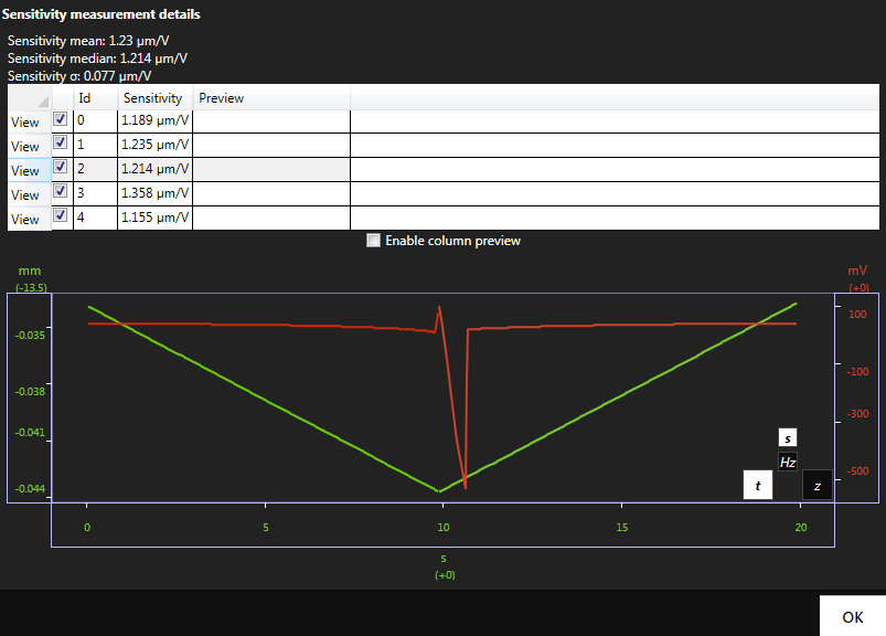
In any case, the curves are stored if you apply the sensitivity value. The sensitivity can also be set manually in the menu “Settings” anytime.
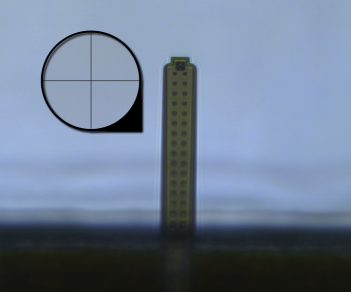
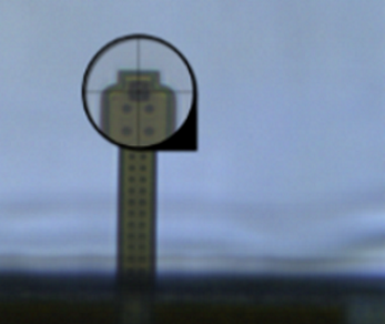
10. Align Probe
In this step you tell ARYA where the opening of the FluidFM probe is located.
Switch the objective to the desired objective for your experiment. Focus on the probe opening. Move the crosshair onto the probe opening.
11. Calibrate Focus Level
This step adjusts the focus height calibrated during installation to the current conditions in order to improve accuracy of focusing on probe at a specific location.
Slight deviations in the position of the probe after gripping and different optical refraction influence the position of the lens necessary to achieve optimal focus. Therefore this step should be repeated whenever the probe is exchanged and whenever the refractive index changes at the location where focusing on probe is desired.
- Switch to the objective with the highest magnification (this will lead to more accurate results) that can still be focused on the probe
at its current position, then press
OKto automatically focus on the calibrated height. You may have to switch the objective and retry if the current objective cannot reach the position. - Manually bring the probe into complete focus.
- Press
OKto save the difference to the calibrated position for future focus on probe request.
If the calibration data is not available, this step cannot be executed and must be skipped.