Component Cabling
Digital connections can suffer from interference that can eventually lead to communication issues with a device. To mitigate this and achieve high system stability the following connection scheme is recommended.
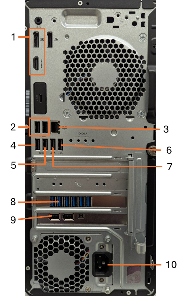
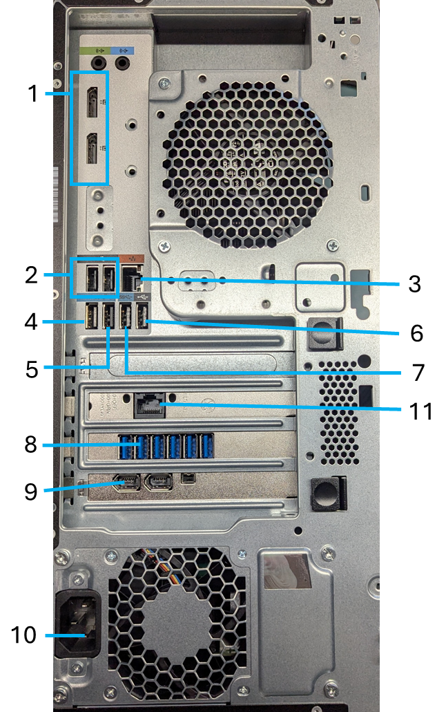
- FluidFM PC components: HP Elite Tower G9 PC (left) & HP Z2 G9 Tower Workstation (right)
| Connection | Description |
|---|---|
| 1 | Main screen |
| 2 | Mouse and keyboard |
| 3 | LAN Cable (uplink/internet) |
| 4 | Microfluidics Control System (v1/v2, if available) |
| 5 | Omnium Control System |
| 6 | USB to ethernet adapter (Omnium network, if 11 not available) |
| 7 | Barcode Reader |
| 8 | Camera |
| 9 | Microscope Control Unit (Firewire) |
| 10 | PC Power Supply |
| 11 | LAN Cable (Omnium/MFCSv3 network) |
Furthermore, the USB cables should not be rolled up and placed on top of the controller box.
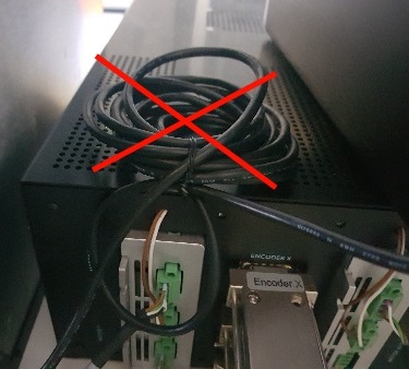
- Don’t place cables on top of the box
Microscope
Olympus
Ensure there are ferrite beads on both ends of the firewire cable that connects the control unit with the Firewire card in the computer.